


https://lora-developers.semtech.com/documentation/tech-papers-and-guides/understanding-adr
What is an Adaptive Data Rate? #
In this whitepaper, we will look at the Adaptive Data Rate (ADR) mechanism. ADR allows us to exploit the advantages of the LoRa? physical layer.
Adapting the data rate in a LoRaWAN? network allows us to easily scale the network, simply by adding gateways. Additionally, using ADR can drastically increase the capacity of such a network.
Let’s begin by looking at a legacy system. Consider an M2M network using FSK-based communications, for example, MBUS. For this exercise, we will consider the 2.4 kbps incarnation of MBUS operating on a single channel. For our scenario, imagine that we are monitoring water use in an urban area, using the metering industry standard of 2500 water meters per square kilometer. In such a case, using typical MBUS settings, assume that we get an urban coverage range of about 500 meters. At this density, figure that this corresponds to 2000 water meters.
Assuming that we transmit at 2.4 kbps and have 64 bytes of payload data, if we run the numbers, we end up only being able to transmit twice a day before we exceed a 1% packet error rate, due to collisions.
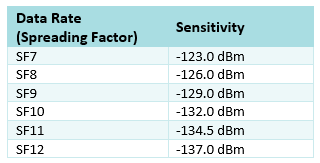
A LoRaWAN network is more robust than this. To understand why, we will look into the behavior of the LoRa modem and the sensitivity available for each data rate (spreading factor?or?SF). For this exercise, assume that the LoRa bandwidth is fixed at 125 kHz.
Table 1: Data Rate and Sensitivity at 125 kHz
Now, let’s also consider the time-on-air:
Table 2: Data Rate, Sensitivity, and Time On Air.
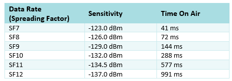
Given the time on air, it is clear that end devices (nodes) closer to the gateway do not need the high link budget that goes along with SF12; nor do they need to stay on air as long. This being the case, using ADR can optimize the SF used for each meter, and minimize the subsequent Time on Air.
ADR is a very simple mechanism that changes the data rate based on simple rules:
- If the link budget is high, the data rate can be increased (i.e. the SF is increased)
- If the link budget is low, the data rate can be lowered (i.e. the SF is reduced)
It tailors the node’s data rate to the available link budget.
Determining the Data Rate #
How does the network server determine the appropriate data rate? Let’s take a look:
The end device’s application sends a message up through the gateway, which simply passes the message along without acting on the data. The gateway in a LoRaWAN network is a simple, low-cost device that converts LoRaWAN packets into IP packets which can be sent over a secure backhaul to the network server. These IP packets include a small amount of metadata about the reception time and signal strength. Based upon the strength of the received signal, the network server determines what the optimal node data rate should be (that is, the spreading factor).
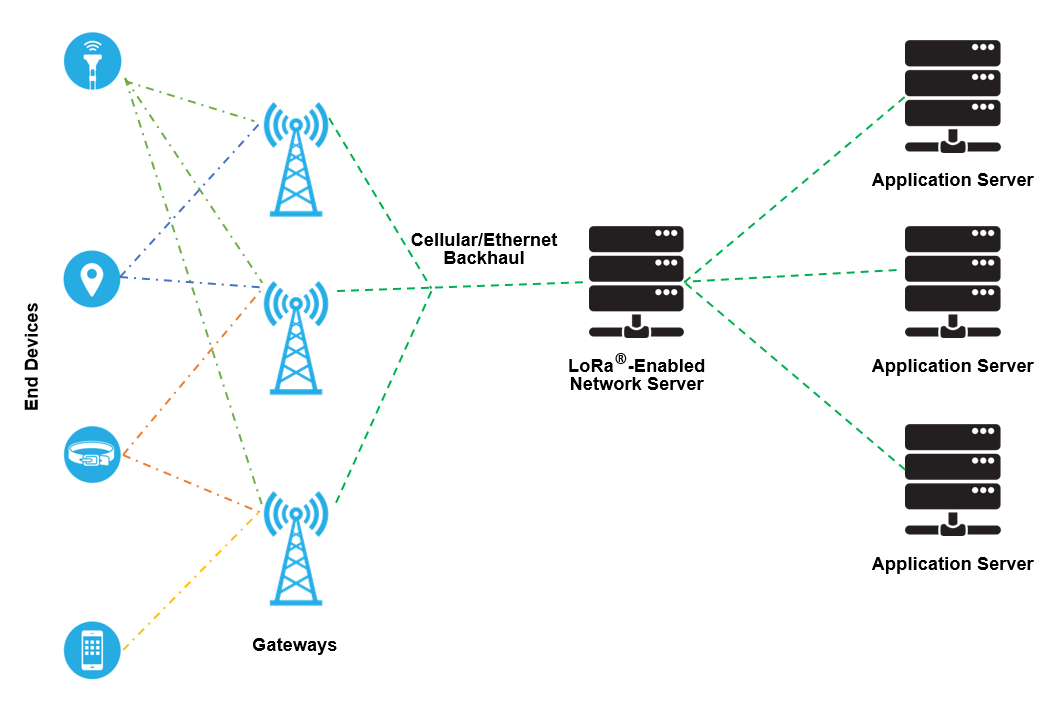
Figure 1
The Media Access Controller, also called the MAC layer, of the network server, talks to the same layer in the LoRaWAN stack of the end-node. A MAC command is then issued from the server based upon its global view of the strength of the signals received from all gateways. The data rate that the node should use, is sent back to the device from the server through the gateway with the best signal strength.
Bit Rate vs. Energy Downlink #
What is the influence of this ADR mechanism when there is only one gateway?
Figure 2 illustrates the result of a simplified case, in which we consider a free space path loss model to estimate the attenuation between both antennas (that of the gateway, and that of the device).
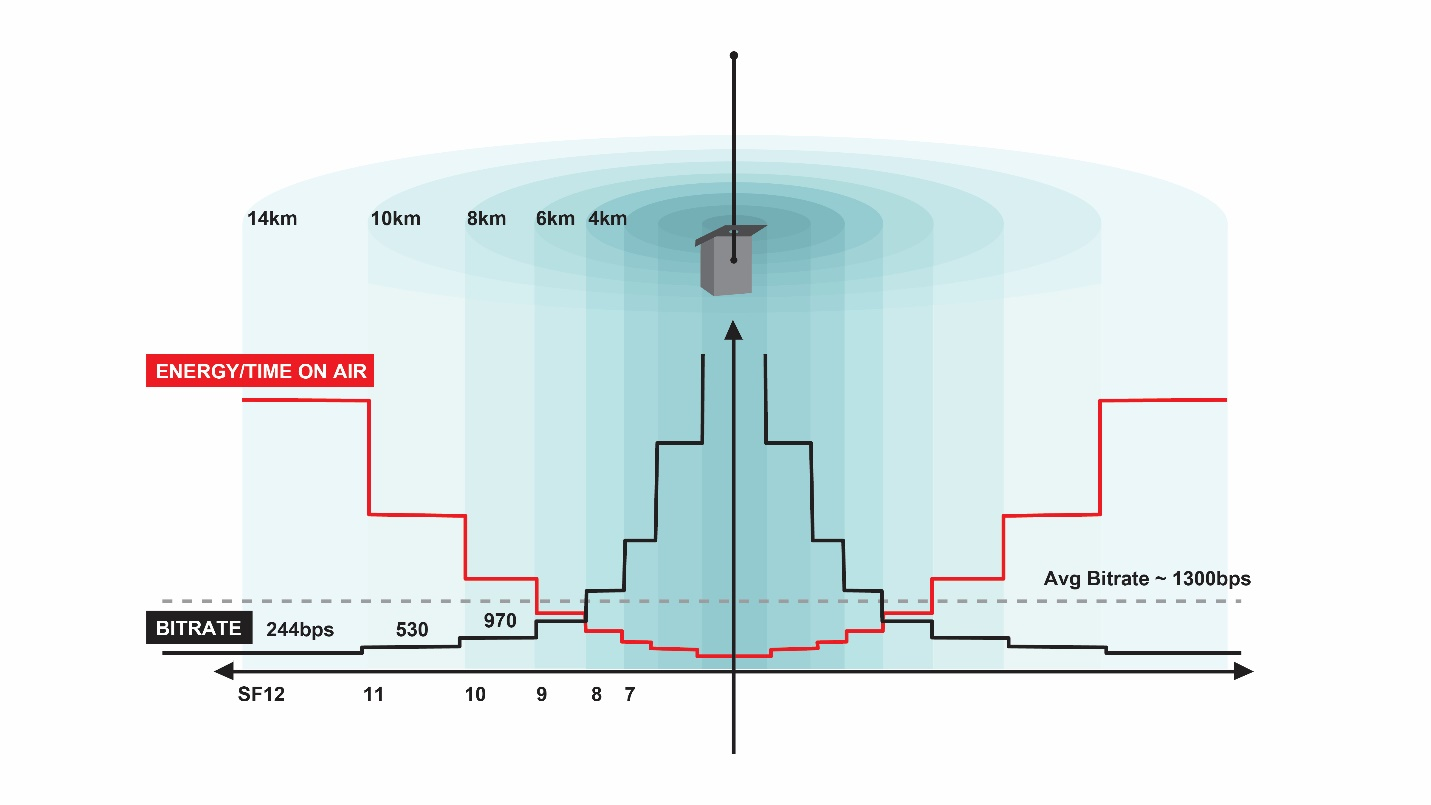
Figure 2
Nodes close to the gateway use a high data rate (e.g. SF7). Therefore, they spend less time on air and exploit the low link budget that they need. For more distant nodes, the data rate is lower (e.g. SF12) and the link budget is higher. In reality of course, the path loss picture is more complicated. It will depend on the specific environment around the gateway, as well as where and how the nodes are deployed.
The important point to keep in mind is that, because the communications are orthogonal to each other:?multiple data rates on the same channel can be received simultaneously.
Moreover, the amount of airtime required for a device to send its payload is optimized, which radically reduces the device’s energy consumption.
Network Capacity Optimization #
Consider ADR from the perspective of the network. Figure 3 shows a single gateway, G1, with a range of devices in a variety of applications.
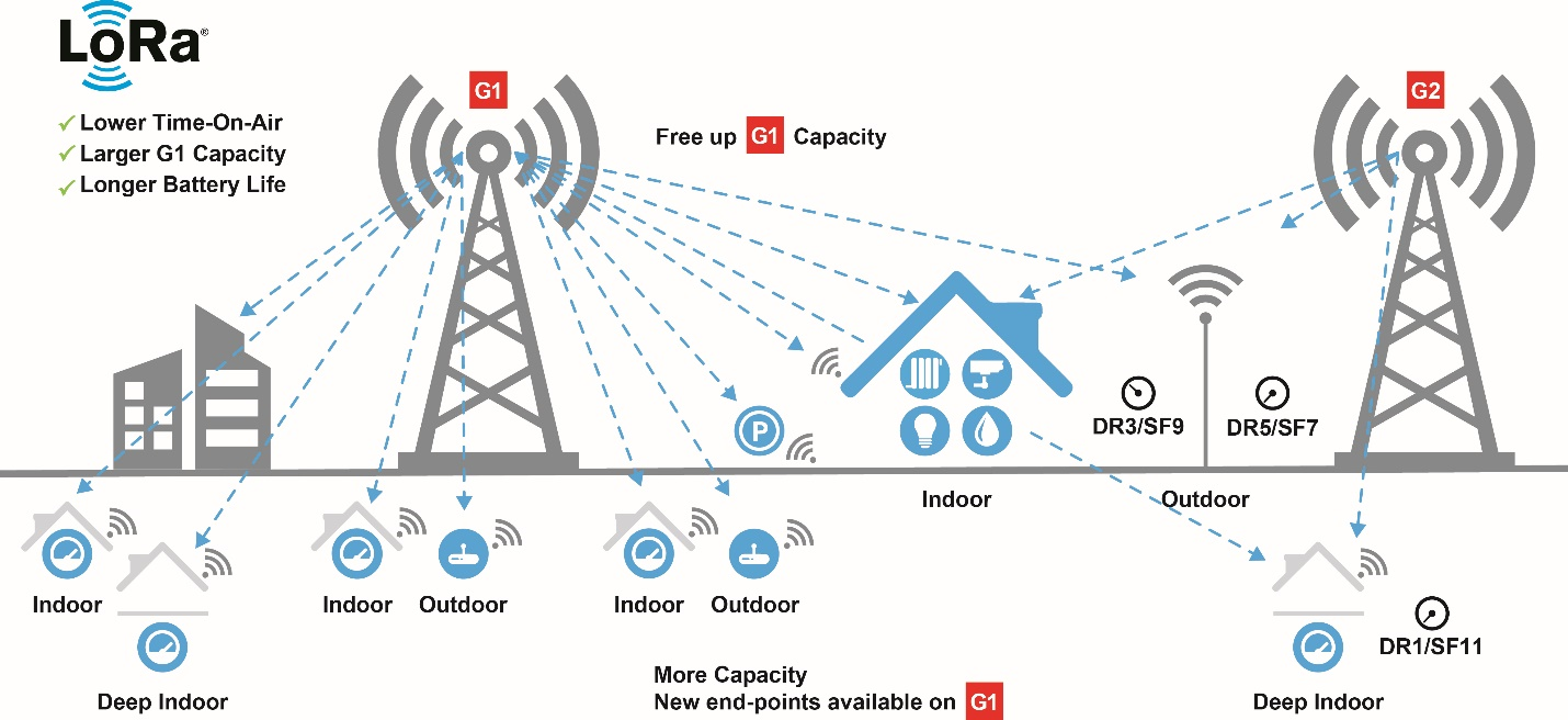
Figure 3
Here we can see that ADR has already been in effect and the nodes have all had their rates adjusted. Even though the gateway can serve all of the nodes, because of the long range of the LoRa physical layer, we can end up ‘seeing’ too many devices from a given gateway, and therefore need additional capacity.
This is easily done with LoRaWAN. Because there are no constraints on which gateway receives signals from a given node, we simply add another gateway (G2). This gateway will also serve any previously-unconnected nodes in the vicinity. More interestingly though, for nodes that are already connected to G1, ADR will do the rest. The nodes closest to G2 will be instructed by the MAC command from the server to increase their data rate, thereby reducing their link budget accordingly.
By reducing the available link budget, we reduce the range of the communication. This will render many nodes invisible to G1 and add capacity to uplinks from, and downlinks to, the end-nodes.
Gateway Limitations #
Before we can examine ADR in greater detail, we need to consider some important design trade-offs that come into play because the gateways are being used in a license-free ISM band. The ISM band, although free, comes at the expense of some practical constraints that are common to any Low Power Wide Area Network (LPWAN).
The first considerations are legal. Some ISM bands, notably in Europe (which is governed by ETSI) restrict the amount of airtime a license-free radio can use. For most applications, this is no problem. However for a gateway that aggregates many applications and must acknowledge a fair portion of the uplink traffic, the legal limit may become problematic.
The second consideration is that, even when not constrained by the law, ISM bands and available filtering technologies do not permit full duplex operation of the gateway, at least not in Europe for instance. That means, when a device sends an uplink, it cannot listen for a downlink.
The result is that downlinks, such as acknowledgements and ADR commands, are expensive when compared with uplinks. A LoRaWAN network can support far fewer downlinks from a gateway to a node than it can uplinks from the node to the gateway.
The other point to think through in the context of LoRaWAN is that end devices operating in Class A mode can announce themselves at any time and then virtually disappear until the next communication. This is important to consider when determining the link budget for a given node on a given application. A fairly conservative ADR mechanism is required here because, while optimizing the data rate is generally advantageous, it must not come at the cost of lost connectivity.
Given these considerations, it is clear that mobile devices cannot use ADR. Imagine a car-tracking application. In such a case, by the time an ADR command reached the node, the propagation environment will have changed so radically that the data rate, and therefore the link budget, would no longer be valid.
Acknowledgement Limits #
To better understand which applications can make use of ADR, and which can’t, we need to look into the control mechanism behind ADR.
While the actual data rate itself is determined by the network server, the ADR mechanism can be invoked from either the network or the end-node. Regardless of which side of the communication triggers the ADR mechanism however, whether or not using ADR is appropriate is determined by the application. ADR is invoked simply by setting the ADR bit in the frame control header. Ordinarily, the end device application decides whether or not using ADR is appropriate. If so, the bit is set – letting the network know that the end-device can have its data rate determined by the network.
To understand this process, imagine a device is connected to the network and has announced itself as ADR-enabled via an uplink (Figure 4). This uplink travels through one or more gateways that simply relay the message back to the network server. By default, it will be sent at the lowest data rate, that is, the longest range setting.
What does the network server do? It waits.
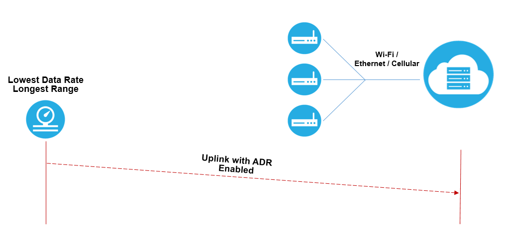
Figure 4
Once the network server has amassed several results, it calculates the median of those results and determines both the available link budget and the highest data rate that can be supported, along with a margin for error, to allow for fluctuation in the channel characteristics. Following the next uplink, a MAC command to change the data rate is sent down to the end device, as appropriate. (Figure 5 shows a MAC command setting the ADR to a data rate of SF7.)
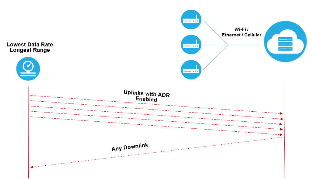
Figure 5
The end device then switches to the new spreading factor and all future uplinks are set at this new data rate. The network server remains aware of any degradation of the channel. It will issue new MAC commands the next time it determines the data rate needs to be changed.
You might be asking yourself:?“What happens if the link is lost?”
The entire time that the end device sends its uplink packets, it also increments the “ADR acknowledge counter”. The counter can be incremented until it reaches a predefined limit, as illustrated in Figure 6.
??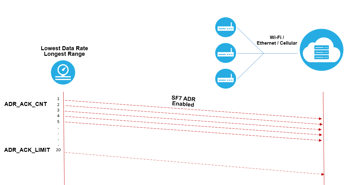
Figure 6
When the node reaches the ADR acknowledgement limit, it sets the?ADR acknowledge request?bit in the frame control header, shown in red:

For?downlink frames, the FCtrl content of the frame header is

For uplink frames, the FCtrl content of the frame header is

Acknowledgement Delay #
After the?ADR acknowledge request?bit is set, there is a predefined delay, the?ADR acknowledge delay,?as illustrated in Figure 7. During this time, the end device waits for the network server to respond to the acknowledgement request. Because the network server might need to respond to several requests, or need to send other downlink traffic, this delay helps make scheduling a given downlink easier for the network server to accomplish.
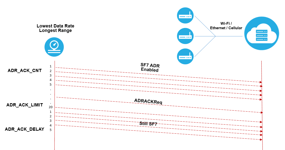
Figure 7
Rather than being specified in terms of time, the?ADR acknowledge delay?is expressed as a number of uplink messages. This keeps the implementation of a low-cost, low-consumption end device simple.
Any downlink packet can include the ultimate acknowledgement from the network server. No special bit needs to be set in the header; the packet is simply treated as also being the acknowledgement.
If no answer is received from the network server by the time the acknowledgement delay period has expired, the data rate will automatically be reduced by one step, as illustrated in Figure 8.
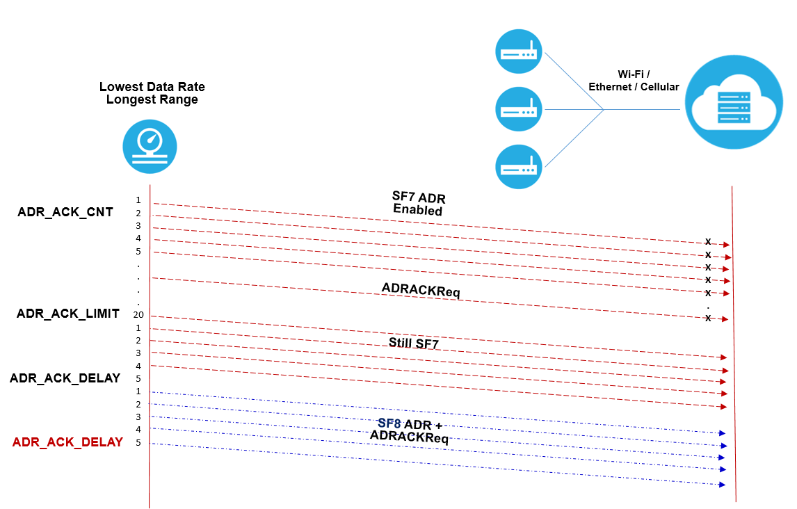
Figure 8
After this one-step data rate reduction, the end device continues sending messages to the server (at this new, lower, data rate) requesting an ADR acknowledgement. Once an acknowledgement?isreceived, the end device uses the new, server-determined, data rate until it receives an instruction to change it again via the normal ADR mechanism. However, if no answer is forthcoming, the end device continues to ratchet down the data rate, step by step, until it gets a response or, assuming the device and network are in Europe, until it reaches SF12 (Figure 9).
Note:?The highest spreading factor that can be used with LoRaWAN varies by region, for instance in the USA, the highest SF is SF10.
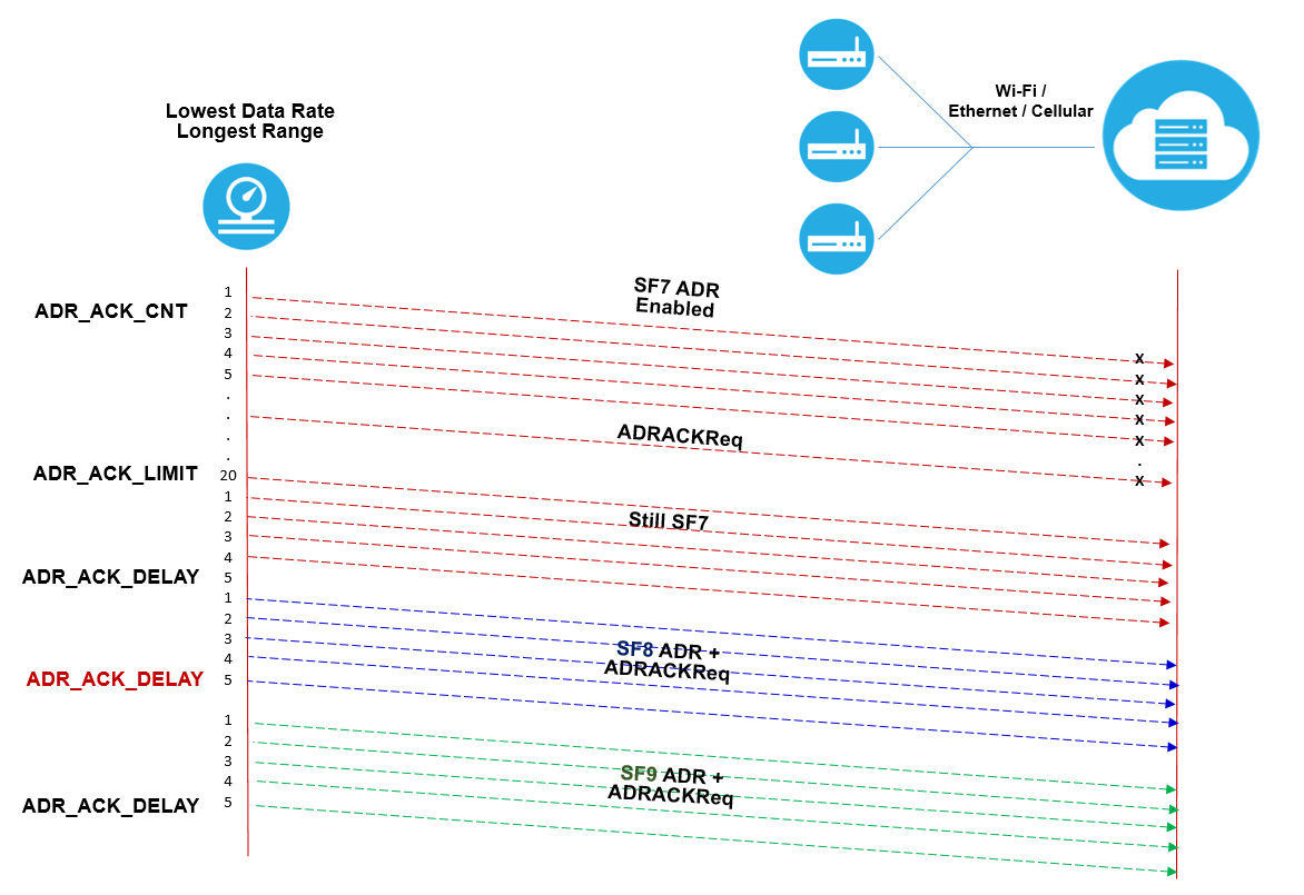
Figure 9
Figure 10 shows very simplified picture depicting a situation wherein a single frequency channel is shared among multiple data rates.
Figure 10
Conclusion #
For static end devices, the ADR is managed by the network server, based on the history of the uplink packets received. This is referred to as?Network-managed ADR?or?Static ADR.
For mobile end devices, the network based ADR strategy does not work because of the unpredictable channel attenuation which occurs as the device moves. Rather, with mobile end devices, ADR is performed “blindly” by the end device. This is referred to as?Blind ADR. For more information about Blind ADR, see the tech paper?An Introduction to Blind ADR.


